
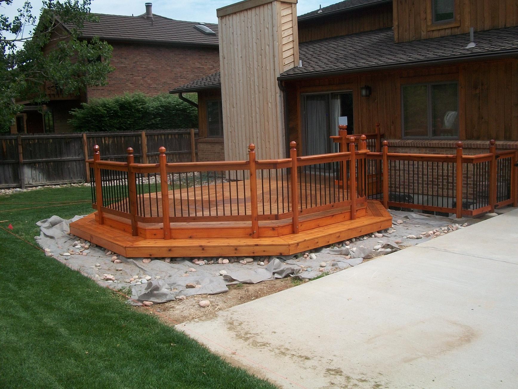
For ten years I’ve thought about replacing the decrepit deck behind my house. I wanted to do something unique to appease my sinful pride. This was the initial concept sketch for my deck consisting of two 15 foot diameter octagons placed side-by-side.
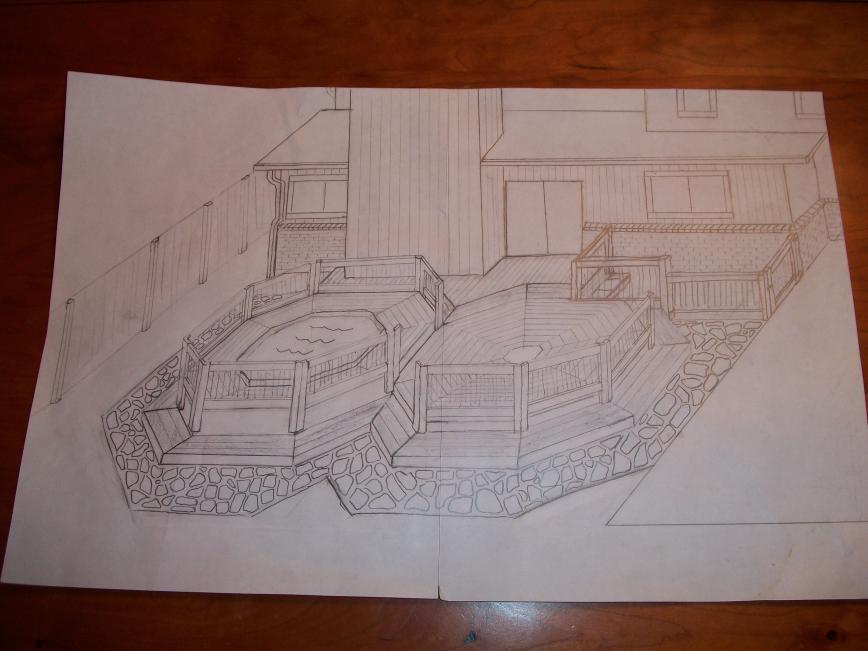
The octagon on the right is only about 14 inches above grade. The octagon on the left is one step up (maybe 7 inches higher) and surrounds an octagon-shaped hot-tub. I wanted the decking for each octagon to be laid out circularly (as shown) to emphasize the octagon shapes.
Contents
Design
Framing design
Although my web searches did turn up a few pictures of octagon decks with circular decking, I found no plans on how to build them. Figuring out how to frame this deck was quite challenging to me — someone with zippo framing experience. Let me emphasize this point with the following disclaimer:
DISCLAIMER: I am not a professional engineer and have no training or experience in construction. I’m a novice. This page chronicles my own deck building experience. I hope you find the information provided here useful, but it is provided WITHOUT ANY WARRANTY; without even any implied warranties. I make no claims as to the structural integrity of this deck design or whether it is fit for any particular use.
I spent hours talking to my father-in-law (who’s built a deck or two before) and to the folks at Front Range Lumber who familiarized me with the various hardware available from Simpson. With their help, here’s the framing design I finally came up with:
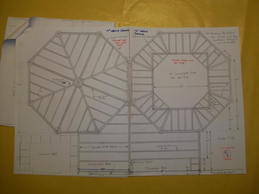
Unfortunately, this drawing is drawn looking north instead of south so left and right are reversed relative to the previous sketch, so I’ll refer to the two octagons as lower (the octagon without the hot tub) and upper (the octagon that’s one step up and surrounds the hot-tub).
Lower octagon design
The lower octagon has one long double-2×10 beam that stretches between two opposite corners, and two more double-2×10 beams that connect at the center of the long beam to form a cross. Each side of the octagon is also a load-bearing double 2×10 beam. The beams forming a cross, split the octagon into four quadrants. All joists are of 2×8 lumber. The joists in each quadrant all run parallel to each other. Note that the joist running through the center of each quadrant is double-wide to provide ample surface area to screw down the ends of the deck boards. Because I could find no hardware to interconnect eight incident double-wide 2x lumber, these four double wide joists don’t run all the way to the center of the deck but instead hang from a side of the small diamond structure which is made just big enough to clear all hanger hardware at the center.
Upper octagon design
Each side of the upper octagon is a double-wide 2×12 beam. (Note that 2×10 beams would be sufficient structurally, but I’m using 2x12s to provide more room to bolt the two octagons together on their common side.) All joists on this side are made of 2×6 lumber because they are so short. At the outside the joists hang from the beams that form the sides of the octagon. On the inside the joists rest on top of (and are cantilevered over) four underlying double 2×10 beams laid out in a simple square. The four concrete piers at the corners of this square have good clearance from the concrete slab for the hot tub.
Post design
Each octagon corner (both lower and upper), has three incident beams (or two beams and a double-wide joist) coming in at 67.5 degree angles. So how do you tie these all together and support them? There’s no post cap I could find that lets you do this. My solution was to notch a post in such a way to support all three beams. I needed a rather fat post to have enough cross sectional area to both support all three beams and still have enough wood left over to bolt everything together. I settled on a post size of 6 inches by 8 inches which I fabricated from two 4×6 rough-cut treated posts that are bolted together. Here is an orthographic three-view drawing of one half of one of my deck posts.
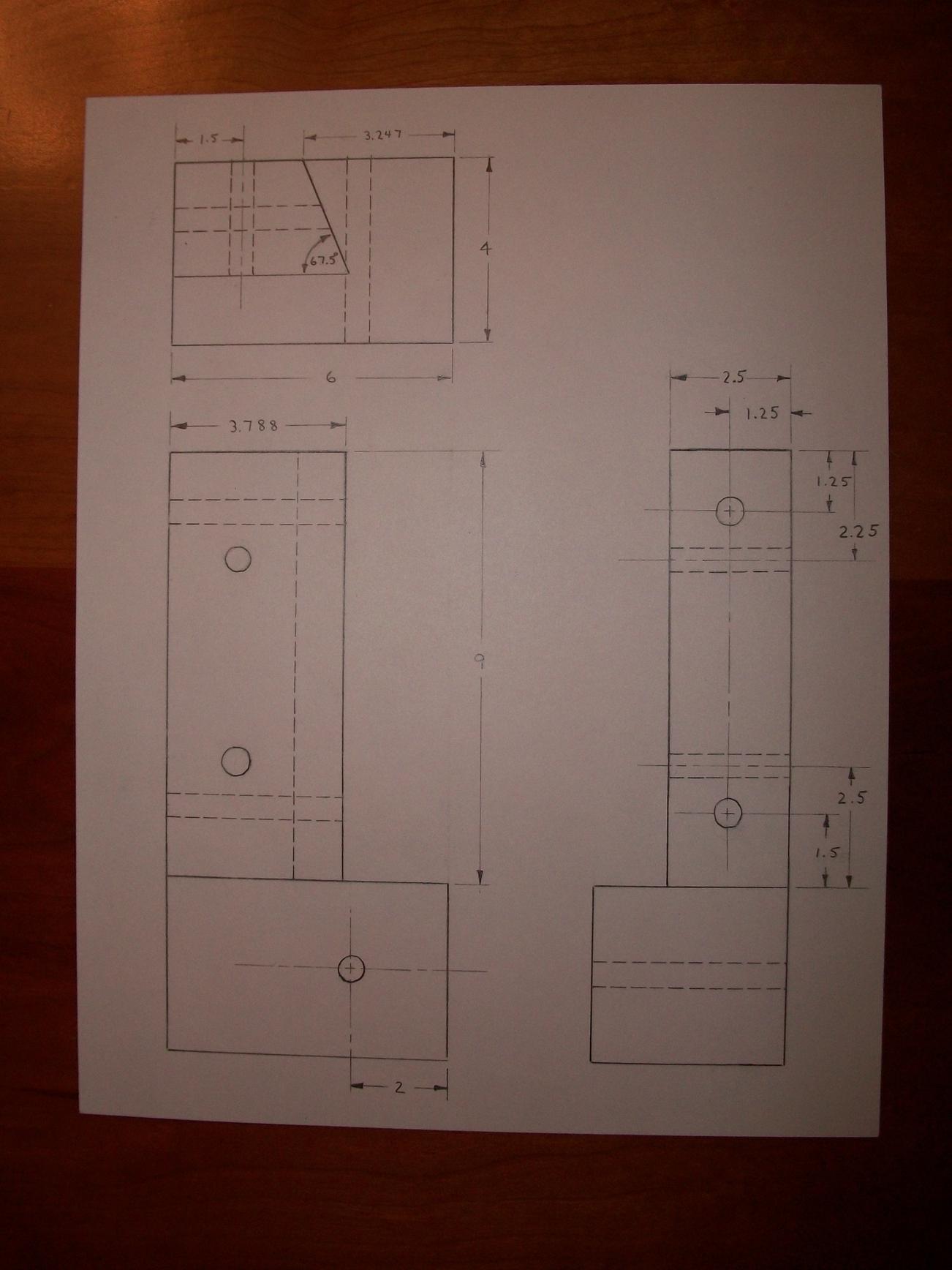
The other half of the deck post is just the mirror image of this drawing. Note that all dimensions in the drawing are in inches and all bolt holes are 1/2 inch in diameter. The notch is shown as nine inches high which is appropriate for a double-2×10. (You’d obviously need to modify this dimension to accommodate 2×8 or 2×12 beams.) It’s important to get the 1.5 inch depth cut just right to match the thickness of your lumber, lest you snap the post when you sandwich the two post halves around the radial beam. The 3.247 inch dimension is chosen so that the exterior face of the side beam will just grace the underlying post corner (so the corner of the post will not stick out underneath the beam).
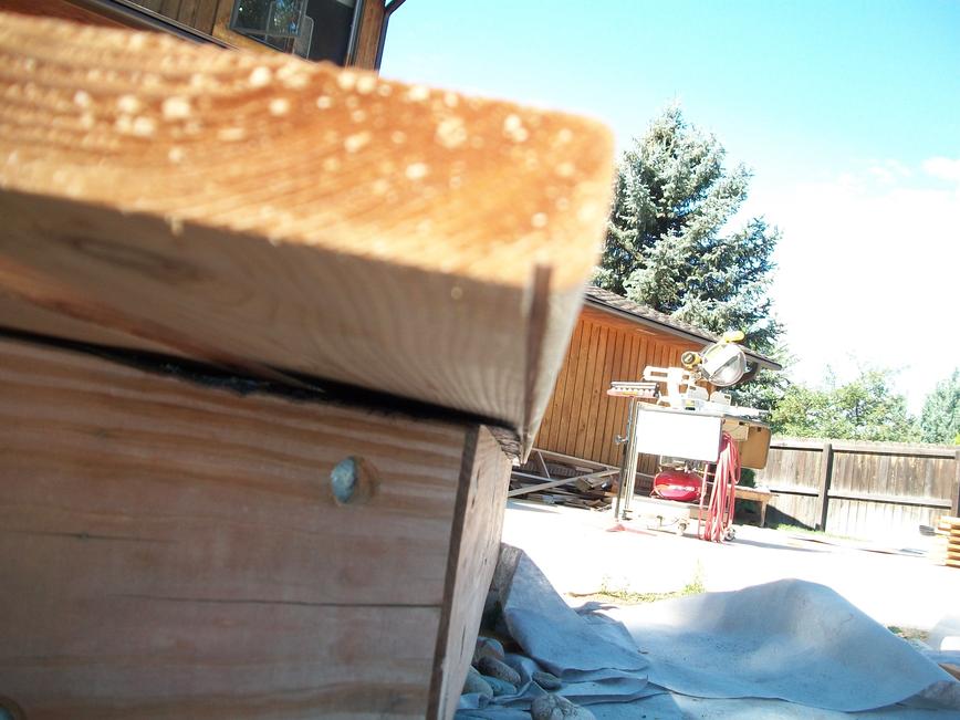
Here are a couple of pictures of my sample-post.

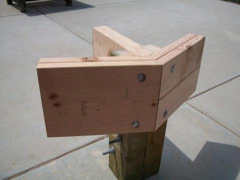
This sample-post served to give me some confidence that I could actually build this deck before I placed the big order for all the building materials. It was also useful during my first visit to the Lakewood building office. They were initially saying I’d need to pay an engineer to approve my post design, but when I showed them my sample post they decided the thing looked so solid I could forgo an engineer’s approval.
Construction
To minimize the delay before having at least a portion of the deck ready for use and also to reduce the risk of lost time and money in the woeful event this whole project flops, I decided early on to build the lower octagon first and save the other half of the deck for some later summer.
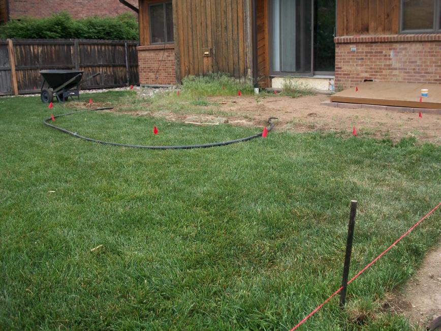
Marking post locations
Once I finished all the drawings required to get my building permit, I marked the post hole locations. I also had to move some sprinklers around. (The black tube is a section of a sprinkler zone that ran under the deck’s new location.)
Digging post holes
Digging the holes to the three foot depth required by local building code was truly a challenge. I started by renting a rather large 9 horse-power auger which worked great until I hit some nasty breccia about 15 inches down. I rented the auger for two days (at $110.00 per day) trying to drill through this stuff, but made very little progress. Then I rented a jack hammer which easily broke up the breccia, but since I could only loosen about 2 inches of rock at a time, several applications of the jack hammer were required on each hole to get them to depth. Getting the loose dirt and rock out of a hole after using the jack hammer was a tedious, and back-wrenching process. (My father-in-law did actually wrench his back.) After accruing over $300.00 in rental fees, I got annoyed and bought my own electric jack hammer for about $600.00. I just wish I had back all the money I’ve spent renting jack hammers and that all but useless auger.
Building a temporary support structure
Usually when you bulid a deck, you pour your piers first; then place your posts; then cut or notch them all to the right height; then connect your beams to your posts, etc. But I needed my posts to be located exactly at the octagon corners. I doubted my ability to get them located accurately enough to make the octagon look true. With so many posts, I thought it would also be quite challenging to get them all level. Lastly, the funny 22.5 degree notch cuts are all made on a band-saw and table-saw — not something I can do once the post is mounted. So instead I built this temporary square support structure out of some 14-foot long 2x4s.
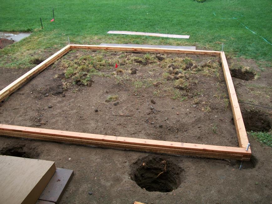
The idea is to build the basic frame of the octagon on top of this structure, with the posts at each corner floating over their respective holes. And then once everything is lined up nice, pour the piers. There’s actually three 2x4s on each side glued and nailed together to provide sufficient strength to support the framing which I estimated to weigh around 1500 pounds (without the joists). Each corner of this square is supported by a threaded rod which itself is stuck in a short length of buried 4×4 to keep it from sinking into the earth. A nut and washer under each corner is used to adjust the height to get the top of the square structure level with the top of the foundation wall of my house.
Making the corner posts
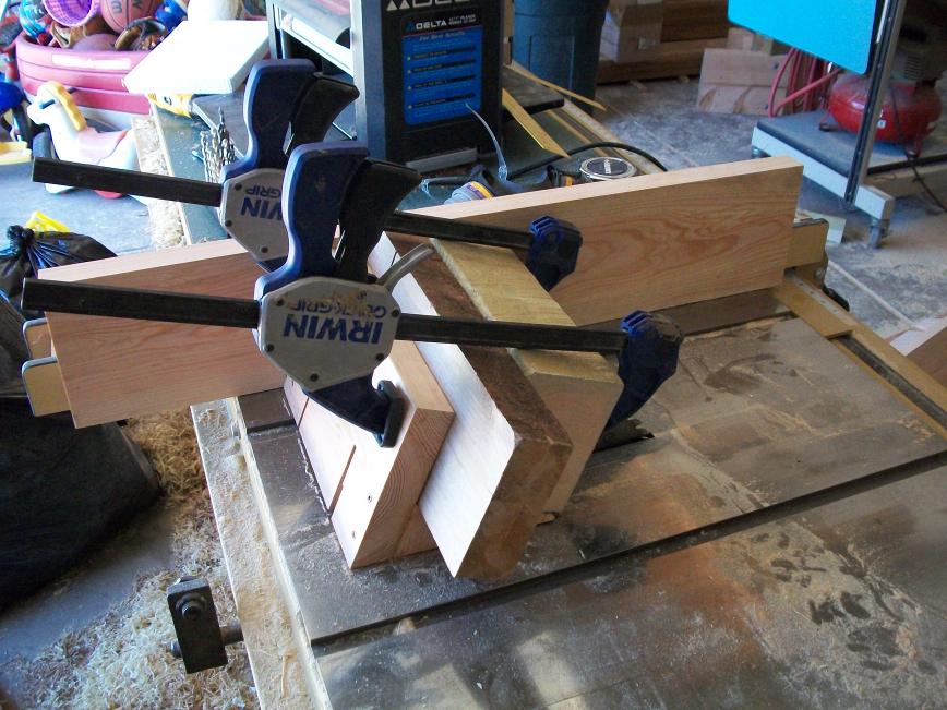
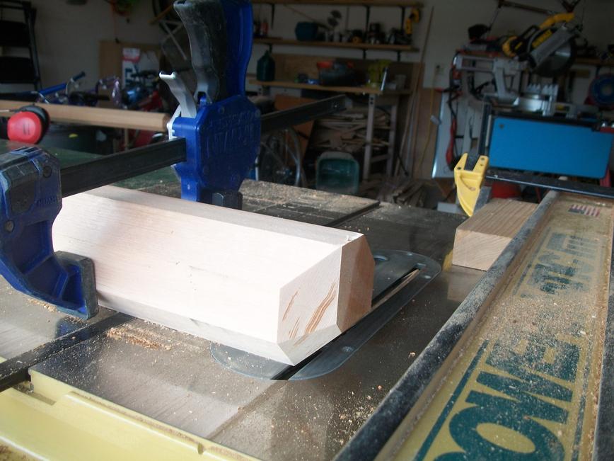
Now it was time to start making posts. Because the lower octagon is so low to the ground my posts are only about twelve inches long. Nine inches of the twelve is notched out so that the post really only extends a scant three inches below the bottom of the beams it supports. (This is actually my major worry about my deck design: that the three inch tall block of wood the beams sit on could split off from the rest of the post. On the bright side, if my deck does ever fail, it can’t possibly fall more than a couple of inches.) Here I am cutting sixteen 12-inch-long post-halves from 4×6 rough cut treated lumber. (I was using clamps to hold the lumber steady because it was a little crooked and I didn’t want it shifting while I cut it.)
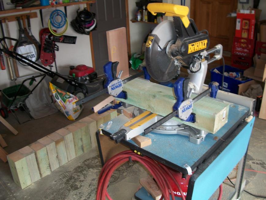
SO MUCH SAWDUST! Although I used a full breather most of the time, there was at least one evening I worked late in my garage without a mask and assuredly breathed in more chromated copper arsenate (CCA) than anyone should. Hopefully I’ll finish this deck before lung cancer sets in.
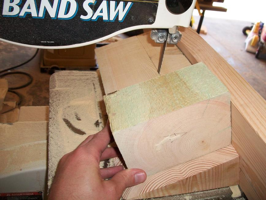
Each post-half required 4 cuts to make the needed notches. Two of the four cuts were trivial, but the other two required a jig to hold the lumber in place as I ran it through the saw. Here’s one of the two jigs I had to make:
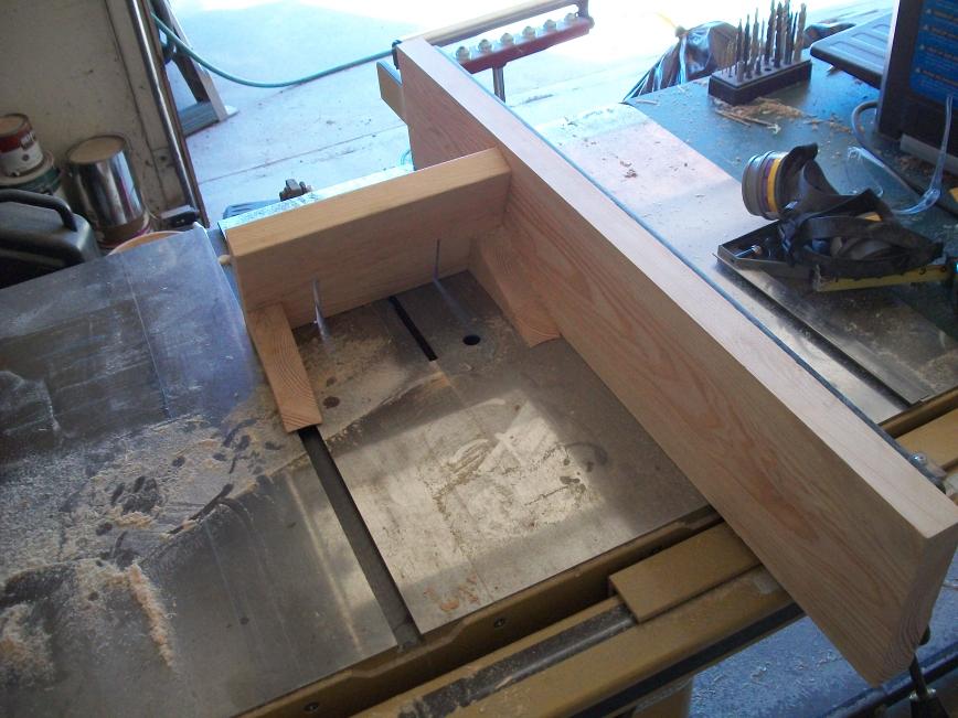
And here’s the other. This one was only needed because my band-saw table only tilted clock-wise. You sort of expect this kind of thing from a table saw, but I was surprised to find this limitation on my band saw.

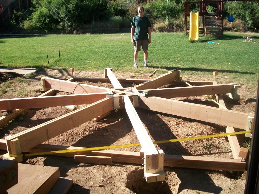
Interconnecting the beams
With the posts all cut, I could start attaching posts to beams (and double-wide joists) and begin framing the deck. One thing I noticed before I started was that not all my 2x lumber was the same size. For example my 2x10s ran anywhere from 9 3/16 inches to 9 7/16 inches in width: a full quarter inch of variance. Normally this isn’t a big deal, but I didn’t want to deal with notching my posts all differently to accommodate this variance so I ended up ripping all my 2x10s down to the standard width of 9 1/4 inches. I figured since this is the nominal size of a 2×10 the inspector wouldn’t complain too much and it did give the added benifit of straightening my lumber. It’s probably worth mentioning that the small diamond structure can’t be nailed with a hammer: I had to buy an air-powered palm nail driver to work in the tight spaces on the interior of this diamond.
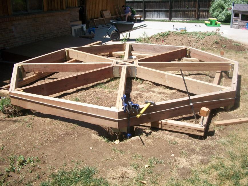
Once in place, I verified the lengths of all the radial beams and double-wide joists (measured from one corner to the opposite corner) were close to their designed size of 188 5/16 inches. I then cut the eight perimeter beams to their design length of 72 and 1/16 inches (measured on their shorter inside). I set them on the posts and stretched a rope around the octagon to pull them all in as tight as I could. I then started bolting them in place. I used a couple of clamps to make sure the beam was well seated in the notch and to hold the beam tight against the post face. A sledge hammer was useful for tapping the post (and radial beam) into proper alignment before drilling the holes. I also counter-sinked the holes from the front so the carriage-bolt heads wouldn’t get in the way of decking and/or steps I intend to mount around the periphery of the deck.
Oct 28, 2010
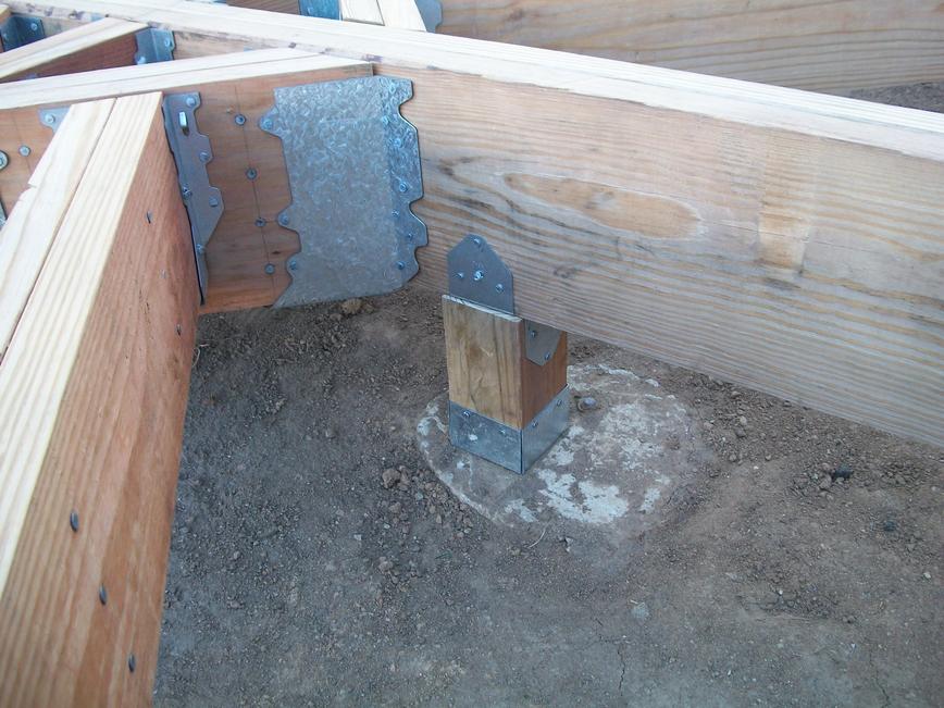
Dropping in the sonotubes and attaching post bases
After a two month hiatus (spent pursuing the creation of this web-site and replacing some rotting siding on my house) I am again working on my deck. I used my clamps in spreader mode between the deck frame and the under-lying square support structure to scootch the deck a few inches to the side giving me access to the holes. I cleaned out the holes (that had partially filled with loose soil from recent rains) and dropped in the sonotubes. I trimmed the tubes to their proper length.
The previous deck happened to have a concrete pier where I could reuse it for my center post. While I had the deck frame slid to the side, I drilled a hole in this pier and installed a wedge anchor bolt to which the post base will attach. It was really hard to find a wedge anchor bolt that was both galvanized and long enough to meet code. I highly recommend wholesalebolts.com. They have a great selection and charge only about 20% of what Home Depot charges.
I scootched the deck frame back into place and then attached the Simpson Strong Tie post bases to each of the eight corner posts. Before I attached each base to its post, I attached a 5/8″ L-Bolt to the bottom of the base. I used two nuts to attach these bolts: one nut on the top-side of the base and one on the bottom. In this way the bolts will be held tight to the base during the concrete pour.
Bridging the deck to the house
I installed the two beams that bridge the deck to the house. These beams simply sit on the house foundation wall and are secured to the house rim joist by lag bolts. I think it’s more typical to use a hanger to connect these to the rim joist, but since my basement is unfinished I was easily able to lag them into place.

Leveling the deck
I was having a devil-of-a-time trying to get everything level with my four-foot level. Is gravity crooked in Lakewood? I began spending my evening hours lusting after absurdly expensive laser levels. Then an old college friend of mine, David Cenedella, told me about a water level. If you have a bucket and some clear plastic tubing, you have everything thing you need to make an extremely accurate level. Just put some water in the bucket; put one end of the tube in the bucket; and fill the tube with water (like you would to make a siphon). Holding the other end of the tube slightly higher than the water level in the bucket will ensure no water siphons out. The water level at the end of the tube is always the same no matter where you move it. Using this technique I leveled each corner of the deck with the top of the beams at the foundation wall. I made gross adjustments by raising or lowering the nuts that the support square rested on; and made finer adjustments with some thin wooden shims. This was so simple and worked so very very well! Thanks David!


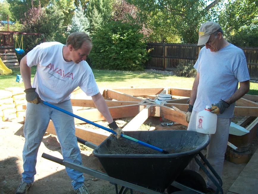
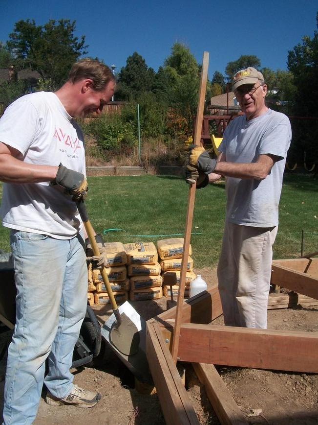
Pouring the concrete piers
My father-in-law came out again to visit and together we hand mixed the thirty-four 80 pound bags of concrete needed to fill the eight sonotubes. We were worried about how hard it would be to get concrete in the small gap between the post base and the top of the tube. Initially I made a huge funnel out of a piece of sheet metal, but then we found a simple sheet metal chute worked wonderfully. The concrete pour was then actually straight-forward. It took us about seven hours of very hard work over two days. Here’s one thing I learned: it’s about four times harder to simultaneously mix two bags of concrete than it is to mix one!
After the piers had cured for a few days, I removed the square structure that the beams had previously been sitting on.
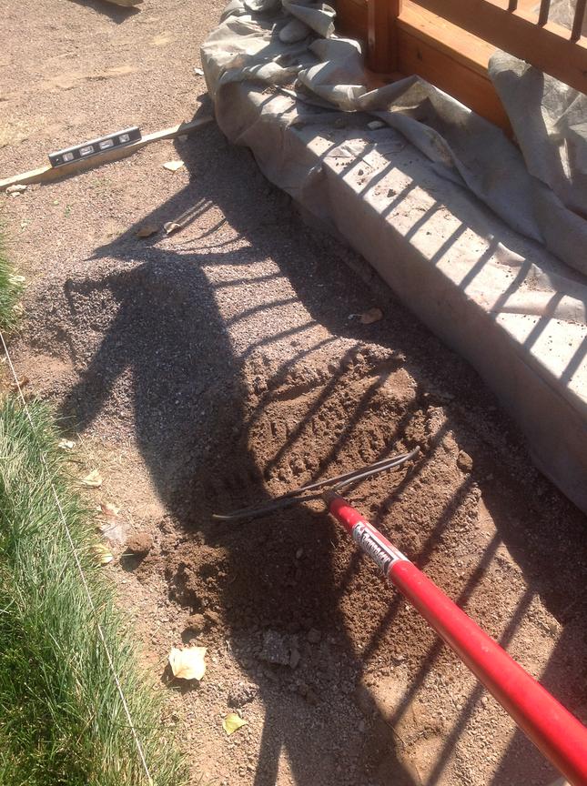
Ground leveling
The ground in my backyard slopes toward my house. Although I made my posts as short as I dared, the ground level at the posts farthest from the house was still an inch or two higher than the top of the concrete pier so the bottom of these posts would be about an inch below ground. This would cause the posts to rot out far faster than they otherwise would. So I spent a lot of time lowering the ground level around and under the deck so that the tops of all of the concrete piers were at least 2 inches above ground and to create a slight ground slope away and to the side of my house. I moved probably three or four yards of dirt (which I’m still working to get rid of).

Installing the center post
My center post isn’t quite in the center because the center of the deck has hanger hardware in the way. Instead it’s about a foot-and-a-half off center under the main deck beam. The only thing of note about this step is that my 16′ long main beam had begun to sag under the weight of the other beams hanging off of it, so I had to get out my car jack to raise it about a half inch before installing this post. Fortunately, this upward force wasn’t enough to crack my new concrete piers.
November 11, 2010
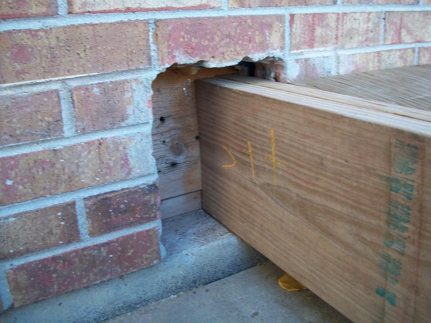
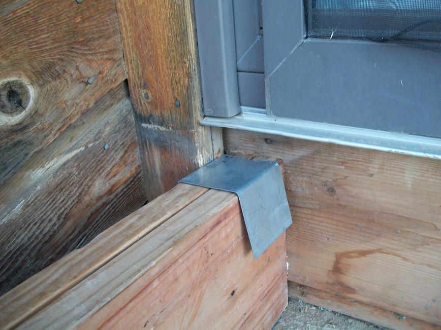
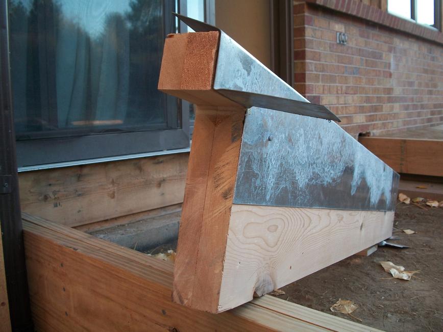
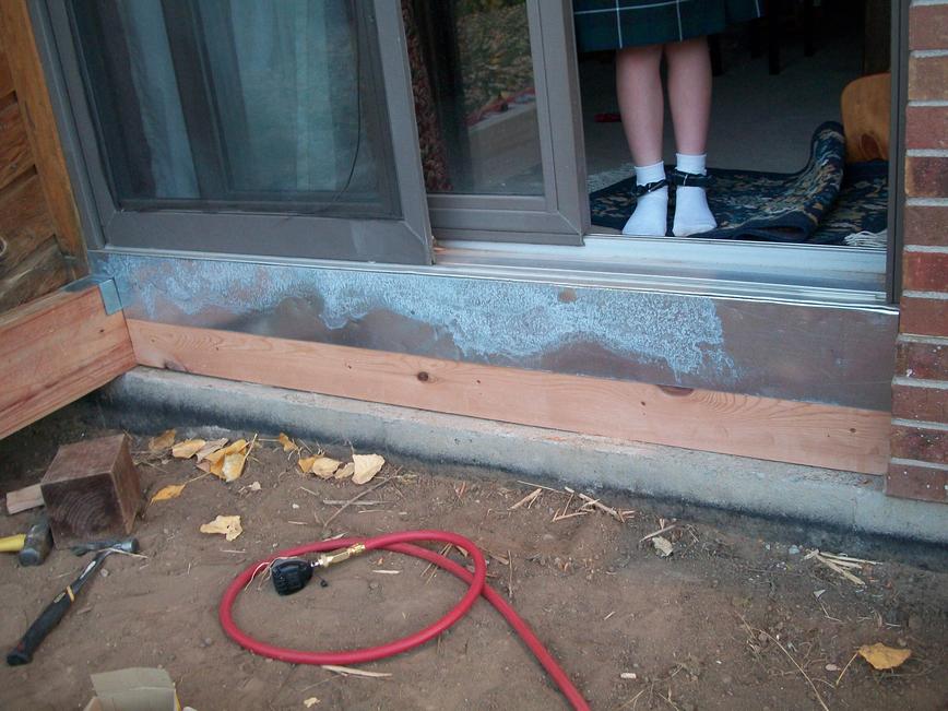
Installing flashing
The aluminum sill under the sliding glass door has been precariously unsupported since I removed the old deck. To remedy this, I shaped a couple of boards to sit under this sill and fill the gap in the exterior wall. I also shaped some flashing that should help keep water out of the wall. Once the boards and flashing were installed, I sealed up all the joints with silicone (not shown).
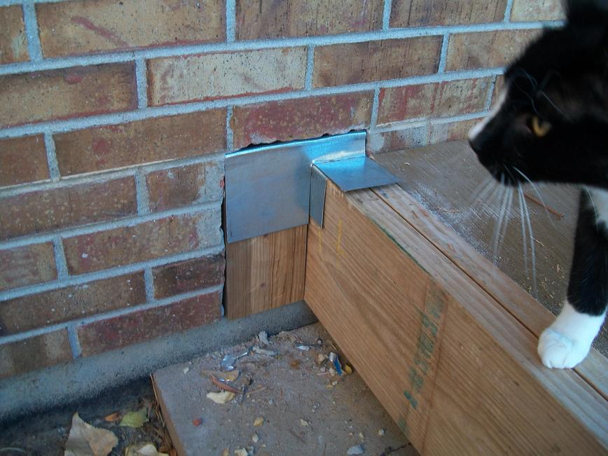
I followed this same procedure to fill the pocket hole in the brick wall.
November 26, 2010
Bolting the beams
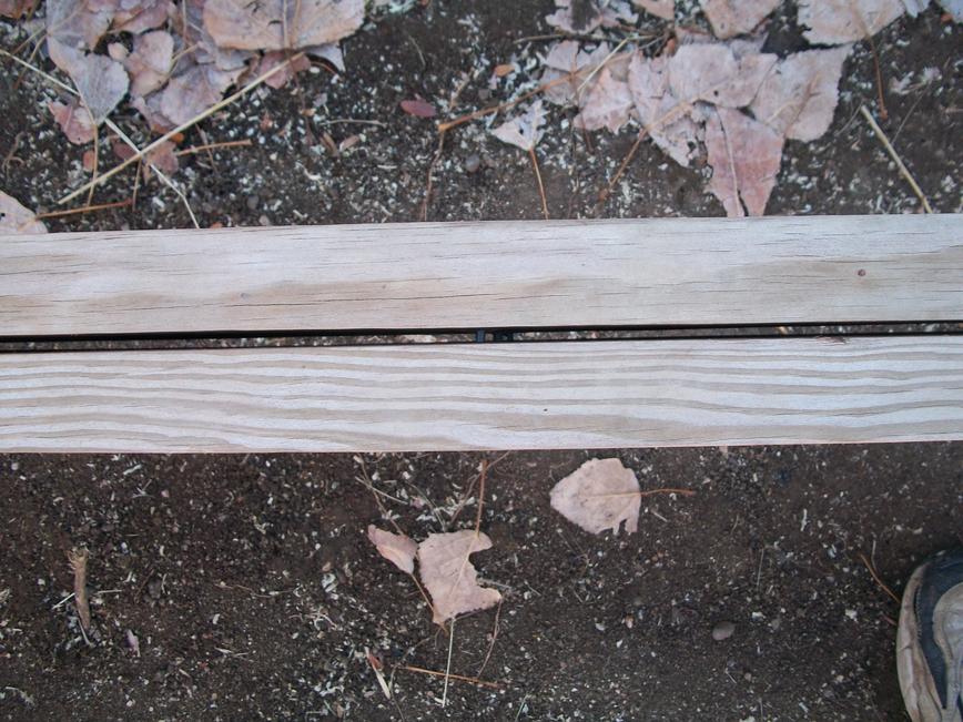
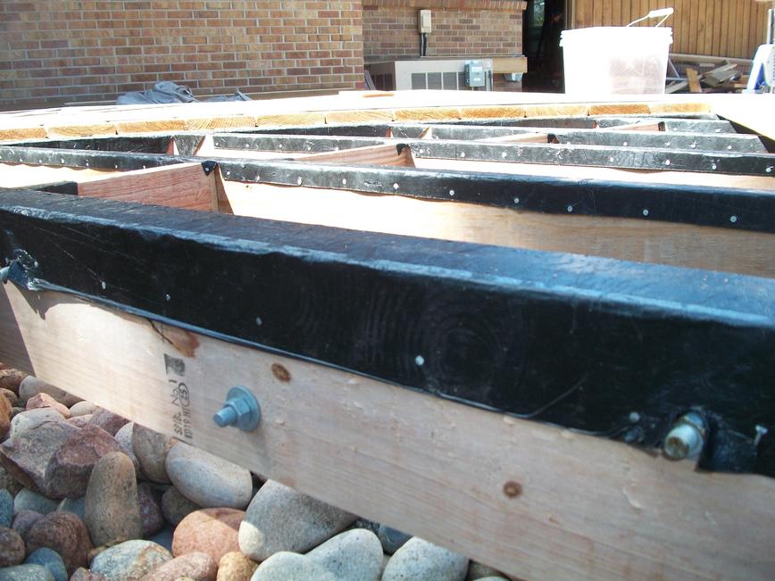
Over the months that I’ve been working on this deck the 2x lumber has cupped and curled. About half of my beams developed sizeable gaps between the two boards as seen here.
If I had angled the nails in when I put them together I suspect I would have prevented much of this gapping. To remedy the problem I bolted all the beams and double-wide joists together.
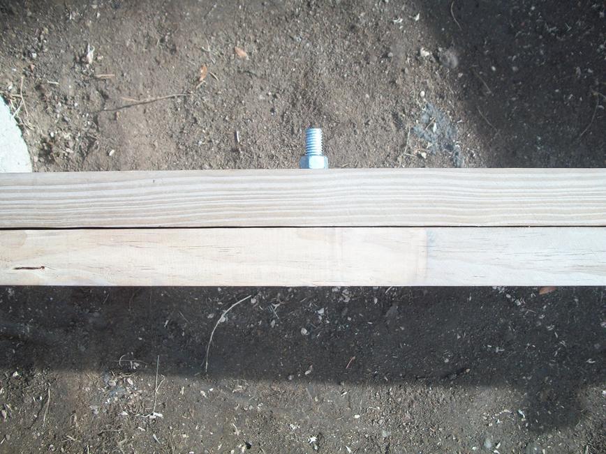
I placed several bolts on each beam placing them alternately about 2 inches from the top and bottom edge of the beam as shown below. (You don’t want to drill any holes too close to the edge of the beam as that would structurally weaken the beam. Check your local building codes for the exact rules.)
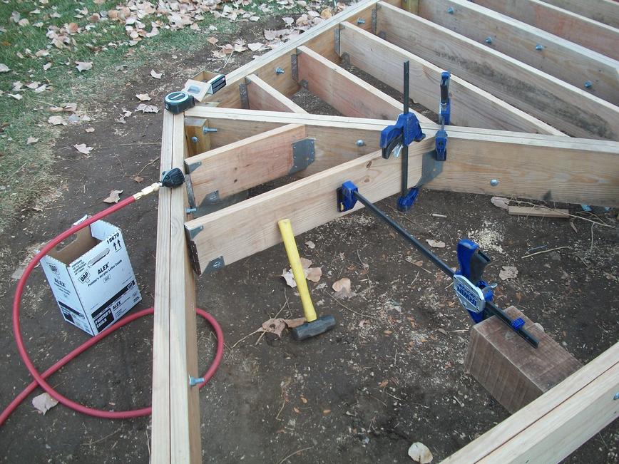
Installing joists
The hangers I installed months earlier (the double-wide hangers supporting the crossing beams and the small diamond structure) gave me some troubles because things wanted to move around on me as I nailed in the hangers. I’ve since learned I should have first toe-nailed the beams into place and then installed the hanger. I did much better installing the joist hangers. Here are the steps I took for each joist.
- I first cut a joist to length (chopped off at 45 degree on one side and square on the other).
- Once I had it to the right length (which would take a couple of attempts as I always initially cut them a bit long), I’d nail on the slopeable/skewable hanger (Simpson Strong-Tie model LSSU28) to the square end of the board.
- I jammed the board into place with a spreader clamp and used a sledge-hammer to tap the joist into proper alignment.
- I toe-nailed the 45 degree side (just one nail) for additional stability.
- At this point the LSSU28 was easily nailed into place.
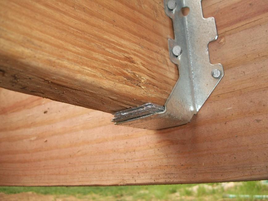
- On the 45 degree side, I used either an SUL26 or SUR26 hanger. These hangers are made of a fairly heavy-gauge metal and were difficult to get into proper alignment by hand, so I used some clamps to hold these hangers flush against the wood before I nailed them.
I used galvanized 10d nails for all angled connections into the beam; but used galvanized “hanger” nails (1.5 inch long nails with a fat shank and a thick head) for everything else (as permitted by Lakewood building code). Here’s a look at the installation of one of my joists.
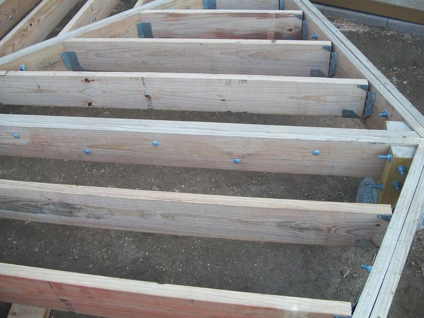
And here’s a look at the deck after all joists were installed.
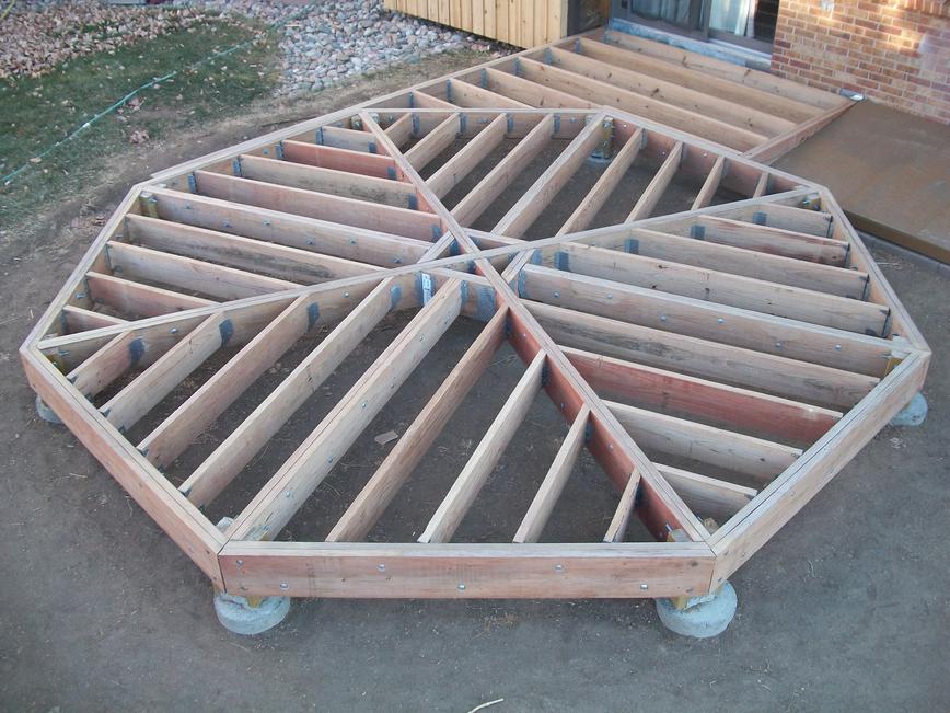
The Lakewood building inspector thought everything looked great and was musing he should show pictures of my deck to the professionals to show them how things should be done. I suspect he was blowing smoke with this remark, but appreciated the compliment none-the-less.
August 26, 2011
Incredible Shrinking Joists
Over the winter months, the framing lumber (which was initially weeping wet with CCA treatment) dried resulting in significant shrinkage in board width and thickness. (Board lengths, in contrast, seemed relatively unaffected.) This caused the tops of every one of my joists to drop so they were an eighth of an inch (or more) below flush with the tops of the beams. This same shrinkage caused the bottoms of the joists to pull upwards so they were no longer seated in their hangers. What a mess! Here’s a look at the top of one of my troubled joists.

I ended up pulling every nail out of every joist, and using hundreds and hundreds of metal shims to get the joists back to flush with the tops of the beams. It turns out that the fat heads of hanger nails are easy to grab with a pair of vice grips which gave me something to pry against to pull the nail; so this job wasn’t as hard as you might think. If I had taken the hangers off altogether it would have saved the time to cut all the shims, but the longer nails used to mount the hanger to the beams had no such fat heads making the removal of these nails all but impossible; and in any case I didn’t relish the idea of repositioning all the hangers. I couldn’t figure out where to buy metal shims, so I cut them from galvanized landscape edging. This was a cheap (but time consuming) solution. Here’s a look at one of my joists after I’ve shimmed it to bring it back to flush with the beam.
Many web-sites offer warnings that treated lumber can shrink significantly, but I’ve found very little documenting how shrinking joists in hangers can lose level with the beam or pull up out of the hanger seat. When (and if) I get around to building the other half of this deck, I’m going to search long and hard to find KDAT (kiln-dried-after-treatment) lumber. I also intend to redesign the second half of this deck to use a cantilever arrangement where the joists instead rest on top of the beams (avoiding the use of joist hangers altogether).
Blocking the joists
Over the winter months, my joists also bowed quite a bit. If I had managed to get the decking on before winter this surely would not have been a problem. To straighten them, I blocked all the joists. This should stiffen the floor up nicely too.
Weed block and rock
I put down a bunch of weed block under the deck and bought some landscaping rock to hold it down. This step may have been unnecessary as I don’t expect much sunlight will make it down through the decking.
Ice and Water
At the suggestion of a local deck builder professional (whom I was chatting with at the building office), I’m placing ice-and-water down over all the beams, joists and post-heads. He claimed that water tends to sit on all the horizontal surfaces under the decking eventually leading to rot. Having seen how my cedar siding rotted away where a joist (from the old deck) was lagged against the side of the house, I decided to follow his advice.
Although the ice-and-water is quite easy to cut to shape (with an exacto knife), it would not stay folded down on the sides of the joists and beams, so I spent a lot of time tacking it down. I was surprised by this as a couple of different people told me this stuff is so sticky it’s impossible to pull up once placed.
I’m only covering a pie-piece of the deck at a time since (as I understand) ice-and-water degrades in full sunlight.
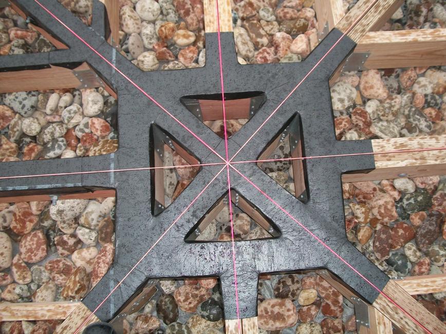
Decking
I first needed to mark the center of the deck. Now you could simply measure to the mid-point of opposite corners, but I decided to stretch some mason lines between corners to get a precise placement. Remarkably, all the lines crossed at a single point. I put a nail at this point which I used to make sure all the decking is placed concentrically.
To deck one pie-section, I started by placing a nail at two adjacent corners of the deck positioned so they fall in the gap between the outer two deck-boards. In my case, this was 93 and 1/4 inches from the center nail. I left these nails in place so I could later use them to mark the cut line for the deck boards.

Later, I’ll be using some cedar decking as fascia boards to cover the sides of the perimeter beams (for a clean appearance). I want the outer deck board to over hang that by almost half an inch, which means it needs to over hang the beam by an inch-and-a-half. I also cut a drip edge on this first board which (supposedly) will help keep the rain off the fascia boards.
For each pie section, I chopped off one end of a bunch of deck boards to the needed 22.5 degree angle and let the other end of the board run long. I jammed each deck board tight against the end of the deck board from the previous pie-section. Once the first deck board was screwed down, I stretched some mason strings along each joist-line to help me keep all my screws in a neat line with the screws in the first board.
I actually used 10 penny nails as spacers between each deck board for my first pie-section, but because the widths of my boards varied by a quarter inch, this made it difficult to match this spacing on subsequent sections. I wish instead I would have precisely placed about every fourth board (assuming some nominal board width) and then simply placed the boards between by eye to achieve a good look. This would have kept the variance in board width from accumulating during placement.
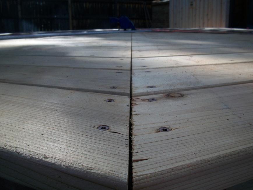
Once all the boards are screwed down, I used a circular saw to cut a gap between the pie-section just finished and the previous pie section. (Be sure to use a high-tooth-count blade to minimize splintering. I failed to do this on my first cut — you can see how the boards on the right show a lot more chipping.) This cut gives the boards a little room to expand with moisture and heat and also makes a nice looking line. The cut depth must be set very slightly less than the board thickness to remove most of the board but without cutting into the ice-and-water below.
I then moved the straight edge to chop off the long ends of the deck boards. To find the right line, I simply stretch a line between the guide nail at the corner and the center nail. I clamped my straight edge so the circular saw will follow this line. After the cut (which again was about 1/32 of an inch shy of cutting through the board), I snap off the boards and flipped up the splinters left behind (seen in the image below) with a knife edge.

This procedure worked fine until I got to the final pie-section at which point I had to carefully cut each deck board to length before slipping it into place. I cut these boards so they fit tight at their ends so I could again cut the nice spacer lines as I did between other pie-sections.
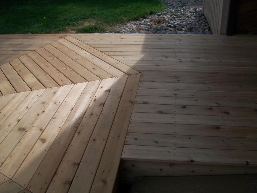
To simplify the task of decking the bridge between the house and the octagon, I carefully setup some mason lines to mark the outer edge of the octagon and then temporarily removed the adjacent deck boards from the octagon. This allowed me to again cut the deck boards sloppy long. Once screwed down I cut the ends off with the circular saw along the line marked by the mason lines; and finally replaced the outer deck boards from the octagon. I should have taken a picture of this process, but here’s a look at the finished work.
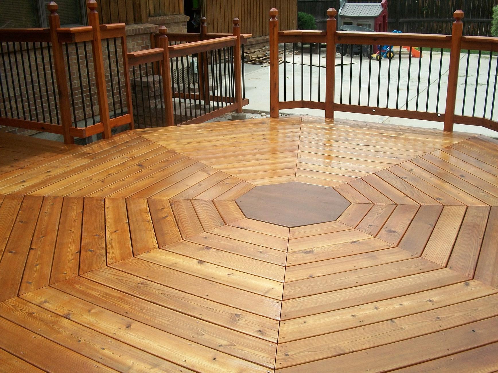
For the center piece, I cut some decking down to about 2-inches wide and glued several together with polyurethane glue and biscuits. (Gorilla Glue sure is messy stuff.) I’m skeptical this will hold together in the weather. If it falls apart I’ll try building something different.
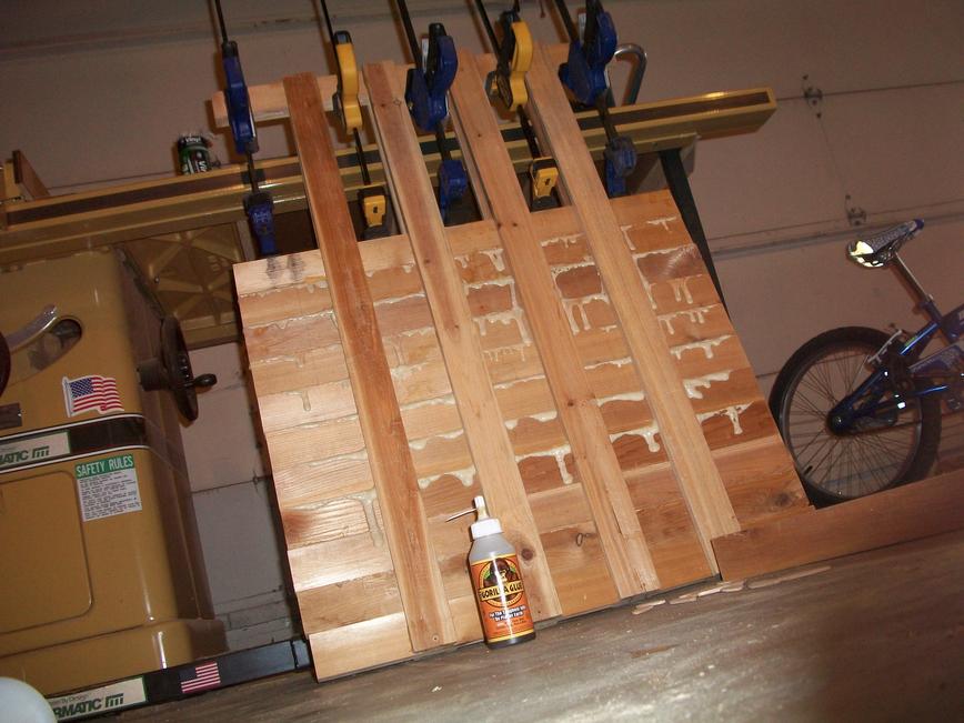

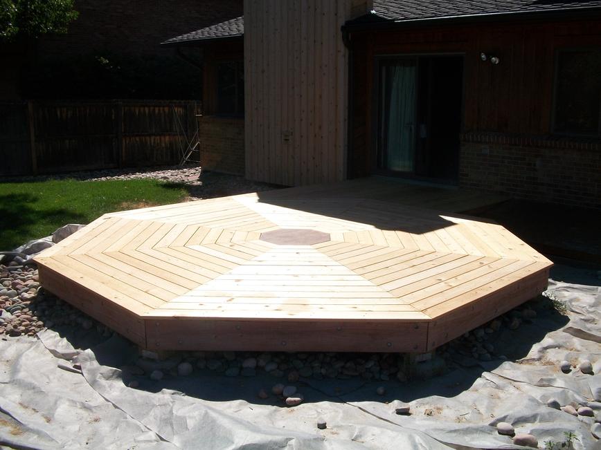
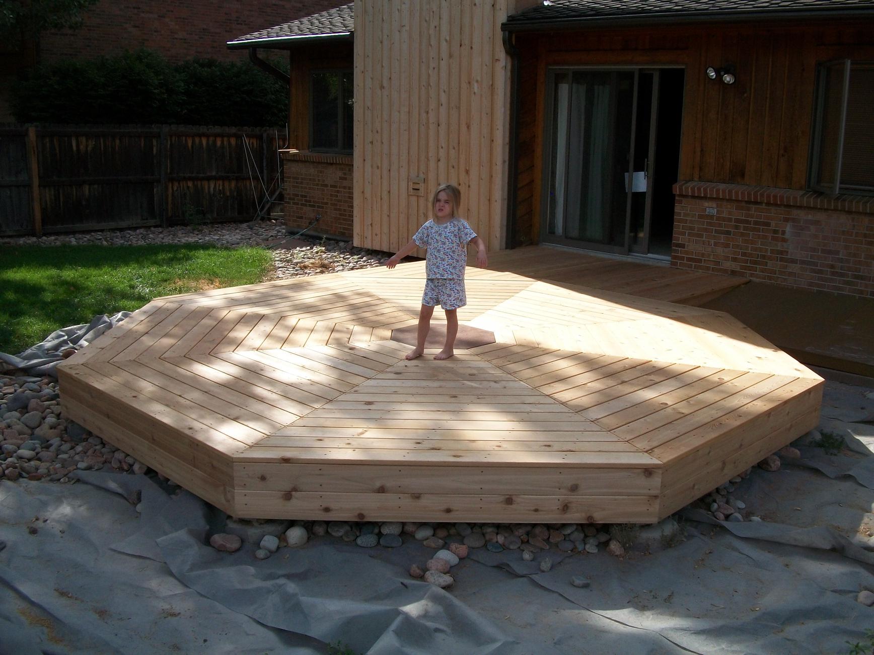
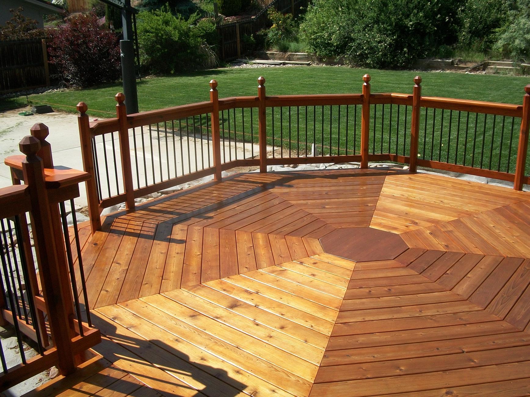
I wanted this center piece to be of a different color, so I went ahead and stained it chocolate brown before screwing it down. Here’s a look at the deck with completed decking.
Fascia Boards
I screwed deck boards to the sides of the beams giving the deck a polished look.
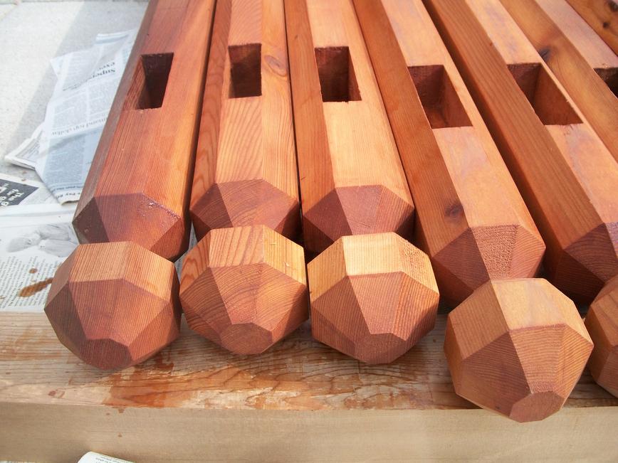
Rail Posts
Keeping with the octagon theme, I first planed some rough-cut cedar 4×4 posts down to a consistent 35/8" x 35/8" and ripped the corners off on my table saw to give the posts an octagon-shaped cross-section. I followed this up with some cross-cuts to fashion an octagon-shaped ball on the post head. This was all pretty darn easy. I then cut slots through the post to accommodate the top and bottom rails. The slots were really hard. Unable to find a mortising bit that would do the job, I actually cut them with a jig-saw; but the wander on the 7 inch blade was bad enough that I had to clean all the cuts up with a hand chisel. A neighbor friend of mine (who happens to be a retired craftsman) tells me I should have used a fluted router bit with a jig to guide the cuts. Live and learn.

I bolted the railposts to the beams that run around the perimeter of the deck. (I had to unscrew a few deck boards to do this — no big deal.) A few posts wanted to lean in or out noticeably (because the perimeter beams weren’t all vertically aligned perfectly). I’ve heard people use washers to correct this problem. I also heard it’s a good idea to install washers to produce an air-gap between the post and the beam (or fascia board in my case) to prevent rot; but it seems to me that concentrating post torque on the smaller washer-sized surface area would lead to wood fiber compression and ultimately a loose post. This is just my guess, I’m likely wrong. In any case I chose to instead use a power sander to knock off a sixteenth of an inch on the top or bottom of the fascia boards to correct my leaning posts.
While I was installing these posts, I also stapled some hail-screen to the same perimeter beams. This screen hangs to the ground, forming a fencing that should keep skunks, foxes, cats and other varmints out from under the deck.
I also had to put a few posts in the ground around my window well. These posts were tricky since they not only had to be plum, square and in good alignment with posts on the deck, but also had to be at exactly the right height (since the rail slots were pre-cut). So I first poured concrete for just one post at the far end of the window well and let that set. I dug the post holes for the other two posts slightly deeper than needed and dropped the posts in, but before I poured the concrete, I installed all my rails around the window-well propping them up as necessary. This suspended the last two posts in proper position while I poured the concrete.

December 24, 2011
Railings
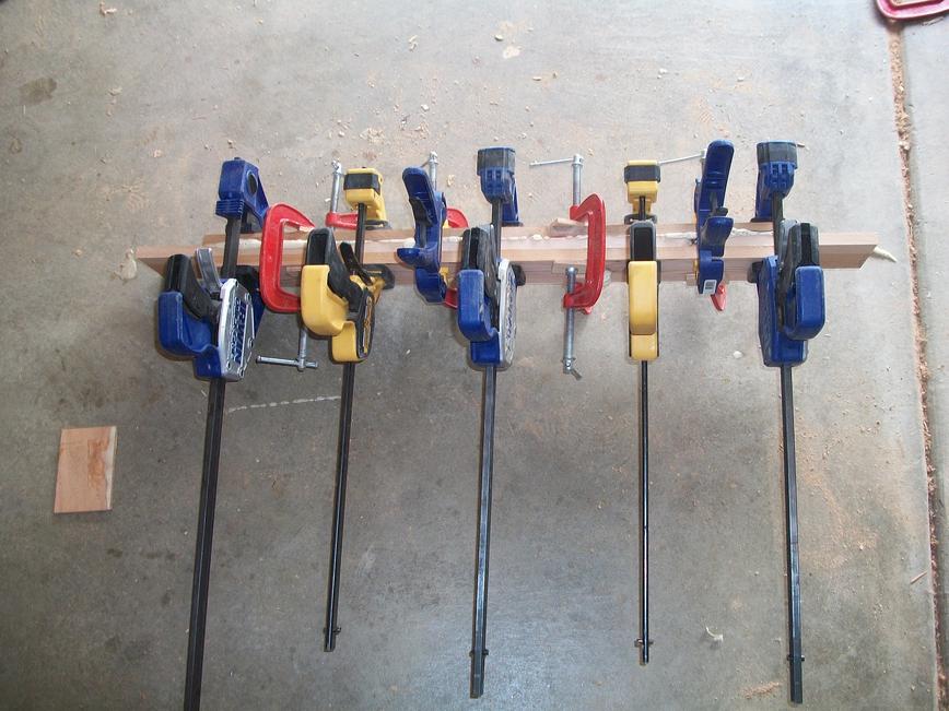
For some reason, I can only seem to find rough sawn cedar in my area, so I used my planer to manufacture smooth and consistently sized lumber. Although the slots in my rail posts were a full 1 1/2 inch in width; I ended up planing my rails down to 1 7/16″ so they would slide in easily and allow for expansion.
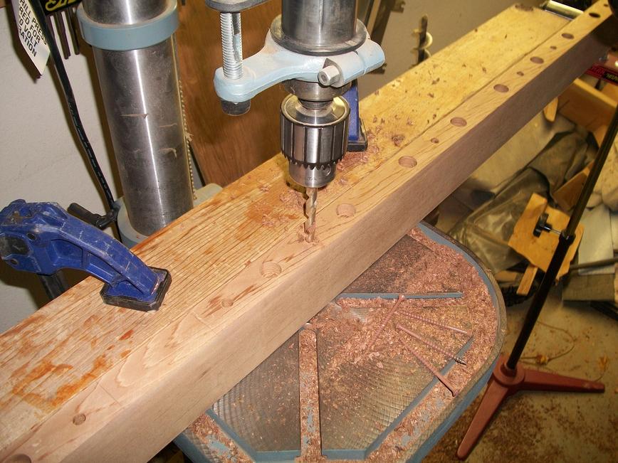
I slid the top and bottom rails into place and then marked positions for the 3/4 inch round metal balusters which I spaced at four inches on center. I then took all the rails down and drilled 3/4 inch diameter holes one half-inch deep at each baluster mark. For the bottom rail, I drilled a quarter inch diameter hole through the center of each baluster hole all the way through the board. This should allow any water that gets in the hole to drain out the bottom of the rail. I also counter-sinked some screw holes from the under side of the top rail that will allow me to screw down the rail caps from the under side.
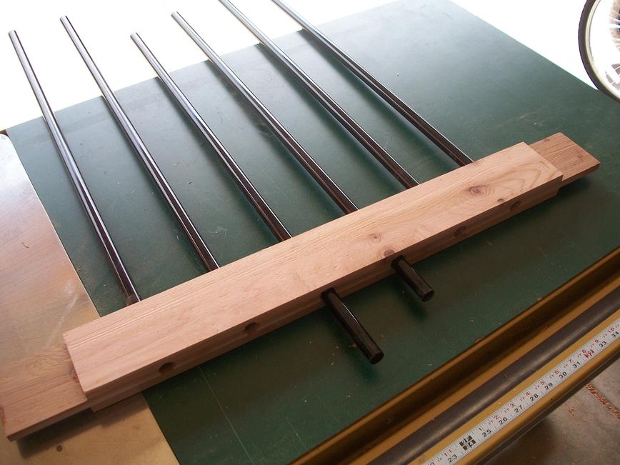
I then put everything back together. Notice that the rail slots for the top rail are an inch taller than the rail itself. Once the rails are slid into place, you can pull the top-rail up by one inch which gives you room to drop the balusters into the holes on the bottom rail and then slide the top-rail back down over the metal balusters. I drove two 3 inch deck screws through the posts at each rail slot to secure the rails. When it comes time to restain the deck, I can remove these screws, slide the top rails up, and remove all balusters in just a few minutes time.

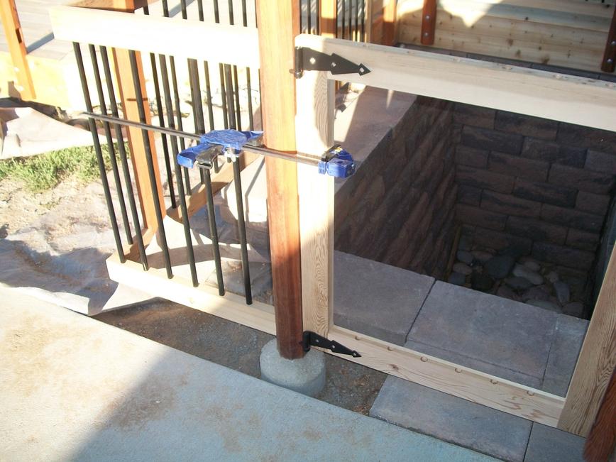
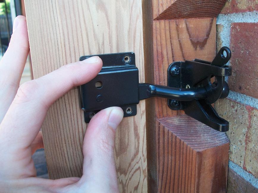
Window Well Gate
I wanted the window well gate to have the same look as the fencing, so I wanted to avoid using the diagonal brace that is typical of out-door gates. I used my band-saw and planer to make a dozen cedar boards that were 1/2″ thick and 3 1/2″ wide. I sandwiched and glued these boards together to make a gate frame that was 3 boards thick on each side, the corners interleaved to make strong joints. (I’m not sure what you call this kind of joint or if it even has a name.) Note that the baluster holes at the top are drilled all the way through so the balusters can be dropped in. I dropped some cedar sticks into the holes before I attached the top rail so the balusters could not slide up once everything was put together. I used a spacer board and some clamps to hold the gate to the post while attaching hinges and latch hardware. This worked great.

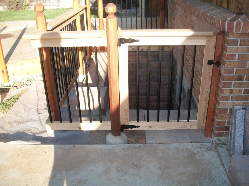
At this point I had my final building inspection. I had a different inspector this time and he didn’t have much to say, which I guess is a good thing.

I was working on my steps around the deck when the winter snows hit. I’ll finish this up and finish with the staining as soon as whether conditions permit, but since this deck is on the north side of my house, this may not be till spring time.
May 22, 2012
Steps
I framed out a single continuous step that wraps half-way around the deck. Only two sides are functional, the rest lead up to a railing and are just for aesthetics. Perhaps we’ll put some potted plants here. The steps are fashioned from box frames that rest on half-buried cinder blocks and are bolted to the side of the deck (and to each other). I had to trim down some 2x4s to use as spacers to clear the rail posts.

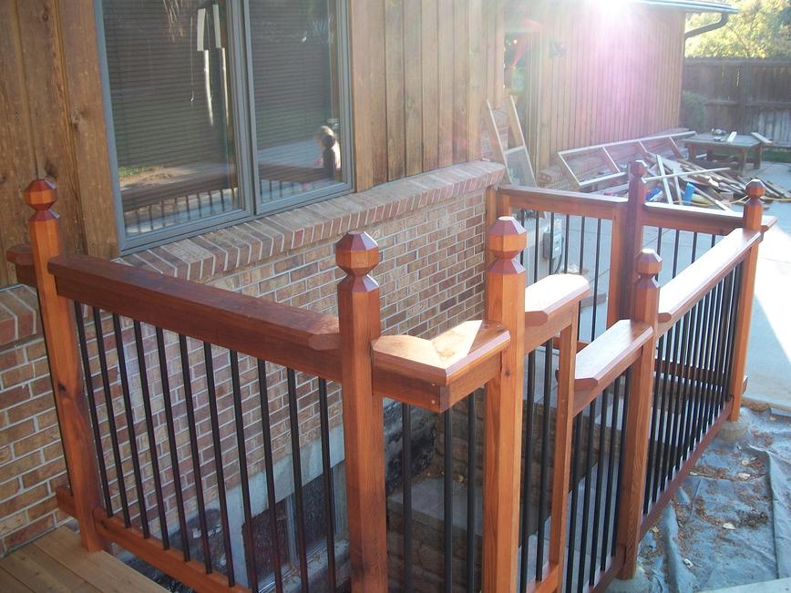
Staining the Deck
I applied two coats of Cabot Transparent Cedar stain. The color matches well with the rail posts that I stained last year. (No fading or darkening.) This stain does have a bit of a sheen. I do like the color contrast of the dark brown center piece, but I don’t like the difference in gloss. Someday, I may sand down and restain the center piece with a different Cabot stain.
November 16, 2012
Flagstone Patio Around the Deck
Here’s my first attempt at a flagstone patio. Because I’m both inexperienced and wholly ignorant of good flagstone installation techniques, I strongly advise you to read other flagstone installation guides and make your own informed decisions about how best to install a flagstone patio. Trying to do anything seen here will probably lead to uneven stones, stones that slide around, smashed fingers, loss-of-eye, excessive weed growth, environmental damage to your soil, the growth of brain-killing fungus in and around your patio, gunfire from angry neighbors, dementia, global warming, lawsuits from multiple government agencies and environmental groups, and the spontaneous evolution of a new globally dominant life form. Proceed at your own risk.
Ground Leveling
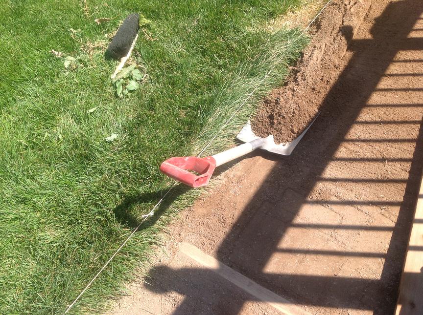
You don’t want to place flagstone on dirt. Dirt is difficult to level, difficult to compact, and susceptible to settling. So I started by excavating a few inches of earth around the deck. I then put down 1-to-3 inches of crusher fines. I’ve read other sites that recommend a layer of road-base, followed by a layer of crusher-fines or sand. Given the hardness of my soil, I suspect I’ll do just fine with only the fines.
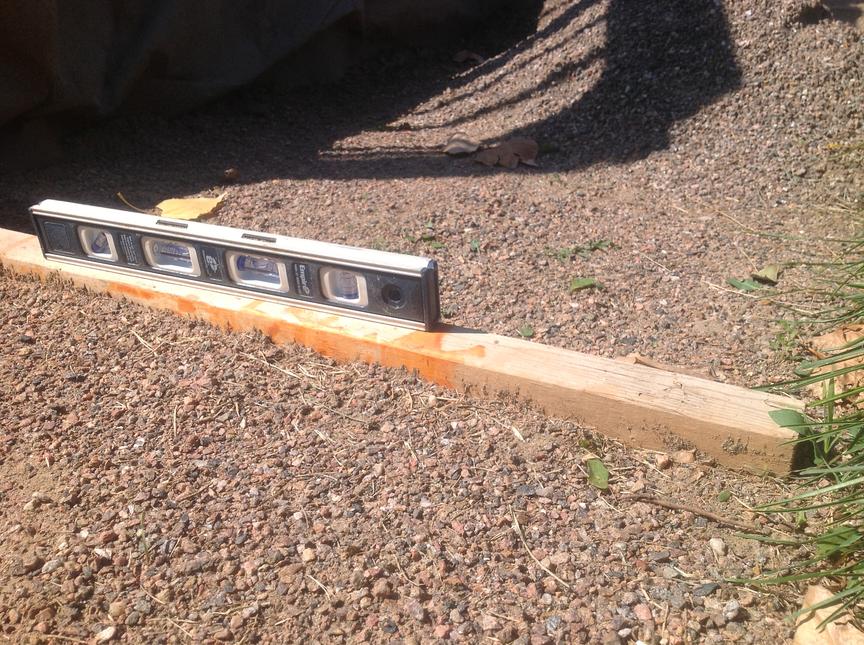
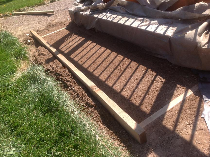
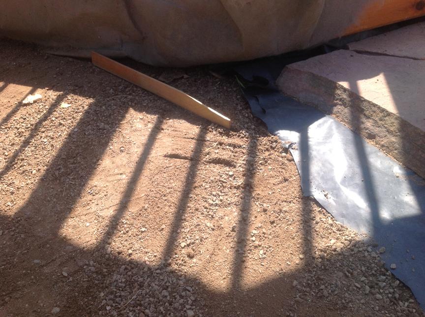
I buried lengths of 2×4 lumber every 6 feet or so, and leveled the tops with the desired level of the fines. I used a small mason level to level each 2×4 along its length and used a long straight edge between three adjacent 2x4s to make sure they were all level with each other.

I spread the crusher fines in a section with a rake, and then dragged a straight edge across adjacent 2x4s to get a level surface.
I shoveled out any excess soil and tossed it into the next section. I bought a tamper to compact the surface, but the crusher fines really don’t seem to need much compaction. If I had to do it over I probably wouldn’t have bought the tamper and just skipped this step.
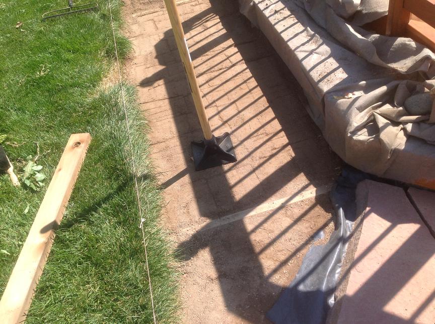
I pulled out the 2×4 closest to the flagstone already laid and patched up the whole using a little board with a straight-edge. I then put down flagstone in this section before leveling the next section. I only leveled one section at a time because I couldn’t seem to avoid disturbing the ground in the work area.

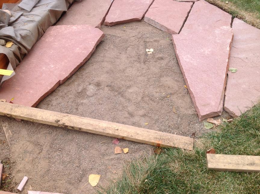
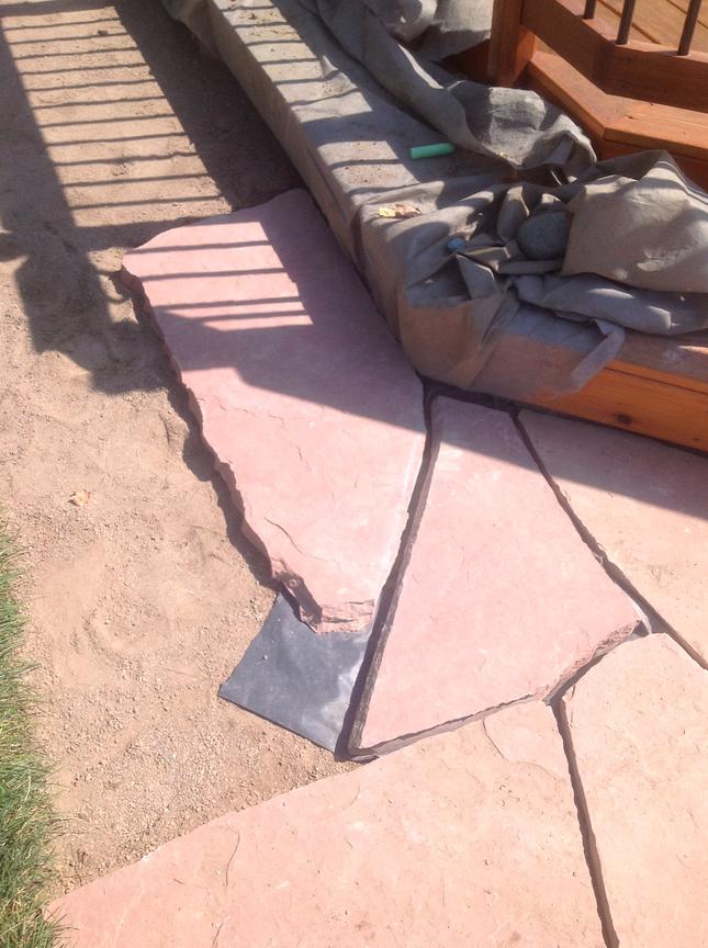
Positioning the Flagstone
I found selecting which piece to lay next a time consuming and laborious task. Each of my stones were nearly 2 inches thick and weighed between 100 and 150 pounds. It was no fun lugging them around trying to find pieces that fit well with the pieces already laid. And finding just one piece that fits well is not really enough: you might find a stone that fills a nook well, only to later find it created a new space that is difficult to fill. For this reason I think it important to always know how the next 2 or 3 pieces are going to be laid. Usually I’d do this by putting pieces roughly into place (slightly laying them on top of each other at the edges) to be sure the next few pieces would cover the immediate work area without much waste. Here you can see how I’m testing the fit of a couple of pieces.
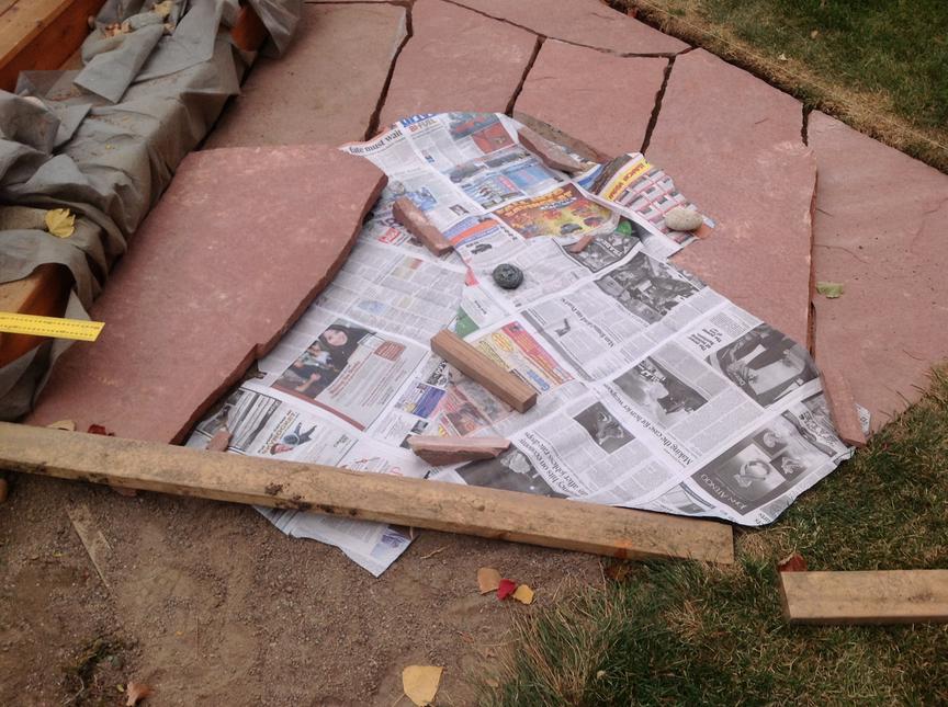
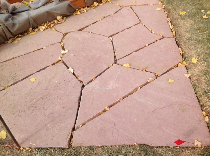
The remaining open space above was the final space in the patio. I only had four pieces left and it wasn’t obvious how to best cover this area with them. And of course they were all big heavy things. To save my back I traced the remaining stones onto newspaper and cut them out. I then used these paper copies to puzzle out how to cover the hole. In the first image below I managed to cover the hole with just 3 of my 4 paper cutouts. I doubt this saved time, but it sure saved a lot of grunting and also kept the flagstone scratch free. To make things look right I had to trim the existing pieces as well as the new pieces. The second picture below shows how things looked in the end. (I failed to take the second photo at the same angle. It’s a bit confusing. Sorry!)
Cutting the Flagstone
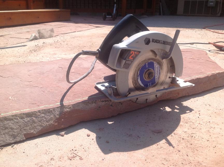
Before cutting flagstone, be sure to don protective gear for your eyes and ears. Little bits of rock would regularly fly into my safety glasses, and cutting rock is really really loud. Here’s a picture of me in my safety gear. I’m still waiting for that first big movie contract.

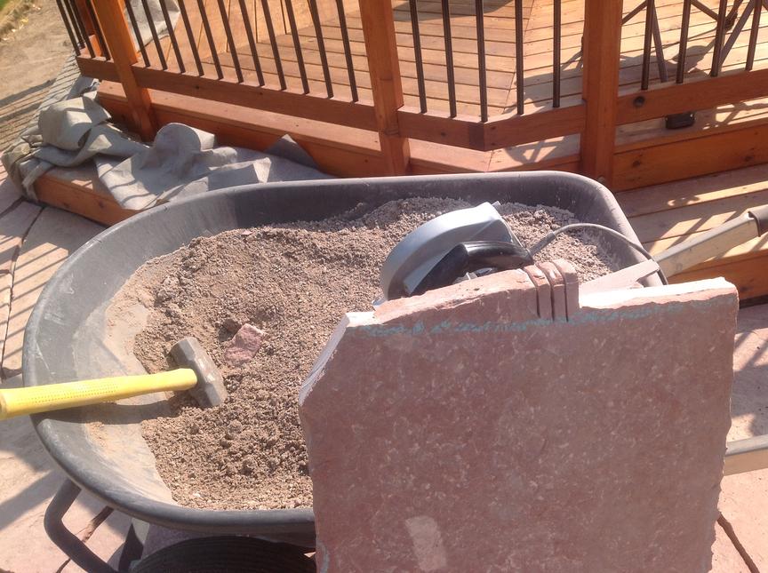
Cutting stone puts out a lot of dust which seems to destroy my power tools. I’m sure there are expensive professional quality concrete saws built to withstand this dust, but I chose instead to sacrifice an old cheap nearly worn-out circular saw that I probably paid $25.00 for 25 years ago. By the end of the project this saw sounded horrible, but it still spins.
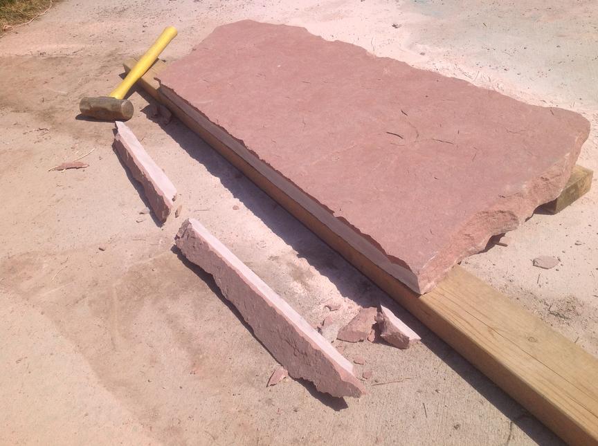
Because I was only putting in a 3-foot-wide patio around the deck, most flagstone pieces needed one straight edge. Some pieces had one edge that was straight enough and I just used it as is, but others I decided to straighten. I started by flipping the stone over and drawing a chalk line (using some of my kid’s side-walk chalk). I set the blade depth so it only cut a little over half way through the stone and made the cut. Then I’d flip the stone back over and tap the edge with a sledge hammer to snap it off. I made all cuts from the back side because it leaves a natural looking broken edge on the visible top side of the stone. Be sure to knock it off from the top (uncut) side: hitting it from the bottom (cut) side will sometimes knock off a layer of rock on the walking surface.


To trim a piece so that it fits well with other pieces already laid, I’d start by slipping the new piece under any pieces already laid that it intersects. I then traced the edge of the pieces already laid onto the new stone with chalk. I’d mark the line to get about a one inch gap. I’d then pull the piece out and transcribe the chalk line to the back of the stone. I did this by hand: I found simply placing a pointed finger from my left hand on the chalk line and trying to touch the same point on the other side with a finger from my right hand works very well. After marking a three or four points this way, I’d just connect the dots to sketch the line. It doesn’t have to be perfect: some imperfection looks better anyway.
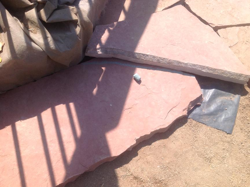

I’d then cut the stone, sometimes making a few straight straight cuts to carve out a curved line. For interior angle cuts, I’d make a series of cuts perpendicular to the chalk line and knock it out with a sledge. There may be better ways to do this. This worked ok though.

Leveling the flagstone
After getting a piece to the right shape and placing it, it would almost always need adjustment either because it wasn’t quite level with the existing stones or because it would rock slightly when you walk on it. I’d typically have to remove a piece just placed three or four times before I got it both level and stable.
Weed Block
I wanted to be sure no weeds grew in the gap between my deck and the flagstone. The plan was to use the weed block I had previously put down under the deck which I purposefully left long to extend out under the flagstone patio. Here I’ve pulled back the rock on some of Home Depot’s “Contractor Grade” weed block fabric. This has only been down for a year and grass has already penetrated the fabric. Complete Junk. Frankly, I’m not sure where to buy good weed block. So I ended up supplementing this fabric with some very heavy black plastic. After I had a large section of flagstone down and level, I temporarily pulled up the stones near the deck and put down some plastic under the deck and under the inner patio. Using plastic like this is bad for your soil and promotes the growth of harmful fungus and mold, so don’t do what I did! If someone knows where I can buy landscaping fabric that will last more than a year in the Denver area please let me know!


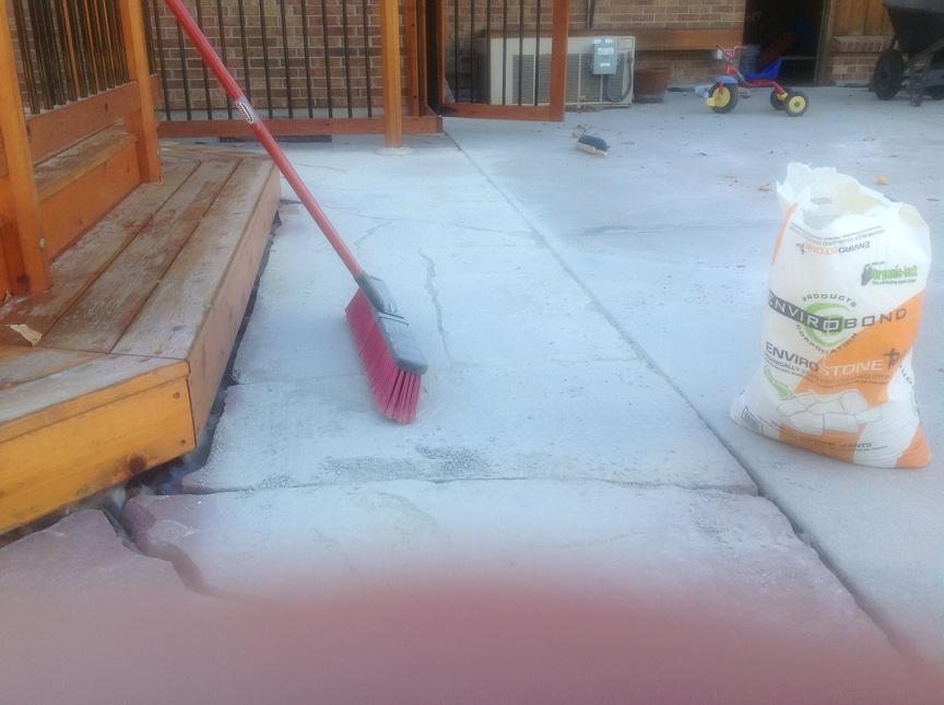
Filling the Cracks
I filled the cracks with a product called Envirostone. You water it into place and it sets up hard; but if it ever cracks you can just get it wet again and repack it. I’m not sure this is the best product, but some friends of mine used it on their patio and were pleased. I started by sweeping it into the cracks. The instructions on the bag then recommend blowing the remaining dust off the flagstone with a leaf blower. This removed some of the dust for me, but not all. I went ahead with the last step of using a hose to soak the Envirostone in the cracks and also to further clean the flagstone surface. I thought things looked good, but after drying I found I was still left with some residue on my walking surface making my previously red flagstone look pink. On the whole, I think the patio still looks very good, but maybe a power washer would have served me better (if I could have avoided blasting the Envirostone out of the cracks). I don’t own a power washer, but I may buy or rent one to try to further clean the surface of the flagstone. Short of that I’m hopeful the red color will return on its own in time.
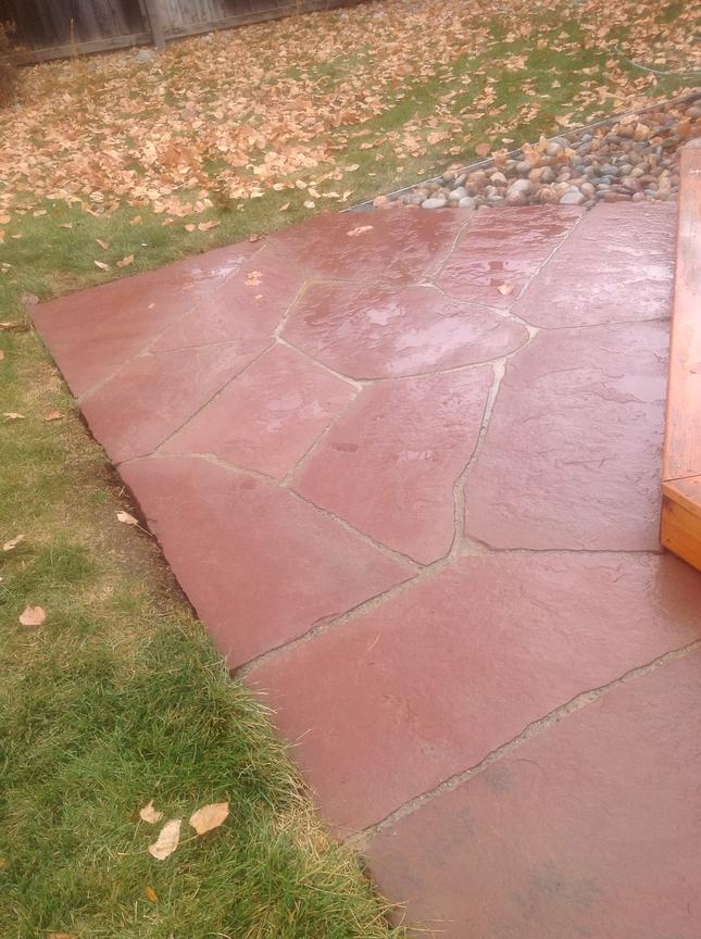
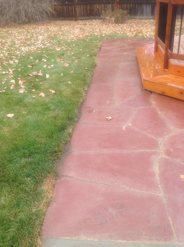
The End!
Hi Matt,
Great work on the design and build, i have been thinking of building the same sort of project at my place in Australia… but with 3 octagons and a square deck in the middle.
I hope you can add more pictures of the finished deck and more detail about your post design, is it possible to add some sketch’s of the post so i can see if i can make the same. I wasn’t going to join all my post together just build the frame on-top of the post’s but i think this would create a nicer finish to the deck.
Cheers,
Chris
Chris,
Thanks for your interest. I will surely post some pictures of the finished deck once I have a finished deck to photograph! But that is surely months away. (If I built decks for a living, I would surely starve.)
As for the post design, I do have some design drawings. I’ll put up a photograph of one the next time I update this blog entry (sometime next week).
Matt
Chris,
I’ve updated the design section of this blog entry to include additional details on my post design. I hope you find this adequate. As described in the post construction section, I needed three saws to shape these posts: a chop saw with a 10 inch blade to cut them to the appropriate over-all length; a table saw with an 8 inch blade to make the two depth-wise notch cuts (one at a funny angle requiring a jig); and a band-saw with a 6 inch mouth to make the two length-wise notch cuts (one of these also requiring a jig.) Making the two jigs was a bit of a pain, but once I had these, making the posts wasn’t all that time-consuming. (I think I made them all over 3 evenings.)
Matt
Matt, I am very impressed with the design of your decking especially the posts. I was wondering if I would so gracious enough and let me borrow your design? Could I please have a copy of the full specs and drawing of your design?
Jean Laurilla
Melbourne, Australia
I’ve had at least a couple of people tell me they intend to use my deck design. If you intend to use my deck design (or portions thereof) please note the following:
1. The dimensions in the framing diagram (if you can read them at all from the photo provided) were all rounded to the nearest inch and as such are not accurate enough to build from. (I only made this diagram to appease the Lakewood building office.) You’ll need to calculate more exacting dimensions using trigonometry (sin, cos, tan). I’d be happy to show you how to calculate these if you need help. Just send me an email. (My email address can be found on the about page.)
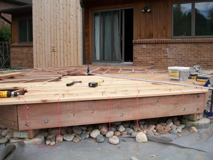
2. The framing diagram for the lower octagon shows double 2×10 beams (3 inches wide) for each side of the octagon. For the two sides of the octagon adjacent to the decking that bridges the octagon to the house, I had to widen the beams to 6 inches. (I bolted on two more 2x10s.) Without this modification, the ends of the bridge deck boards would not be supported. If you look closely at the photo of the framing you can see the extra 2x10s for one side. (Unfortunately this photo was taken before I widened the other beam. That one was harder to fix because I had to first temporarily remove two short joists.)
3. If you use 4×6 rough-cut timbers to build the posts (like I did), make sure you find (or special order) high quality treated wood. In particular, be wary of 4×6 landscaping timbers as these, I believe, are typically low quality.
Good Luck!
Matt
Hi Matt,
Love your deck project! I have a similar deck and was wondering if you calculated the load capacity? or at least a close guess? lol
The Octoganal portion of my deck was built by the previous owner so i’m not 100% sure on all the details. 2×6 treated decking, 2×10 supports with 4×4 posts. The posts span about 8 feet tops. I was going to place my hot tub on it but I’m a bit skeptical. The overall deck is huge and well built for sure. Any help would be appreciated.
Thank and congrats on your deck!
Jon
Jon,
No, I’ve only made sure I was under the limits specified by the standard beam and joist span tables. My beams are all fairly short and my 2×8 joists are spaced only about 14″ oc. My deck has a nice firm feel to it, but I’m still not sure I’d put a hot tub on it.
I did have a statics class during my electrical engineering studies, and if hard pressed I might be able to calculate load capacities correctly; but I’m really not qualified to be giving advice about whether your deck can support a hot-tub. I’m really a novice at construction and am learning as I go.
When (and if) I get around to building the other half of my deck, I’ll be including an 8 foot diameter octagon shaped hot tub that when full weighs almost 5000 lbs. The hot tub covers around 50 square feet, so that’s 100 lbs per square foot which (I think) is a much greater load than most decks are designed to handle. I’ll be resting this hot tub securely on a concrete slab with the deck built up around it, but I guess that doesn’t really help you.
For anyone to calculate whether your deck can support a hot-tub they’ll surely need a sketch of your deck that includes post, beam and joist sizes; joist spacing; and post positions. They’d also need to know the size of your hot tub, it’s full weight, and where you intend to place it. With all that information I should think a PE could tell you whether your deck can handle it and possibly tell you how to augment your deck so it can.
I’d be interested in hearing what you find out.
Good luck,
Matt
Excellent project! An incredible project which you took 2 years to finish 50%. Looking at your octagon, it reminds me of Ba Gua (http://en.wikipedia.org/wiki/Ba_gua). And your deck design is a perfect one to deploy such staining pattern. Ha ha ha!
Thanks Henry,
I’m glad you like the deck. As far as my slow progress goes, I blame it on perfectionism, inexperience, and the time demands of home and family. Frankly, I’m not sure when I’ll start work on the second half of the deck. Don’t hold your breath.
Matt
Did you ever get the flagstone in place? I’m about to start a backyard deck and hardscaping project which is how I stumbled upon your blog. I’d love to see a how-to as glorious and detailed as the one you did for your deck project for the flagstone work. 🙂
Eric
Sadly, it’s still only about half done. In any case, I wasn’t planning on providing many details on how to install a flagstone patio because there are already so many web pages covering that topic. The only thing I’m perhaps doing a little different is cutting each newly placed piece to nicely follow the contour of other pieces that are already laid. Perhaps I’ll include a picture or two describing how I do that.
I’ve been distracted by more pressing home repair projects. Most recently my electric cook-top broke. So I put in a new one. Doesn’t sound like that big of a deal, but the old one had this goofy down-draft ventilation which was not only ineffective, but the hole in the middle of the stove was always filling with grease, popcorn, spaghetti sauce, and everything else. So I yanked that out; took the vent out of the wall; bricked up the hole in the wall; replaced the crappy aluminum wiring with copper; re-ran the phone line through the wall (which previously came in along side the vent and dropped down to the basement through the under-cabinet shelf); installed a nice glass-top electric stove and bought a traditional over-the-stove vent hood; took down the cabinets above the stove and shortened them to make room for the new vent hood; stripped and refinished that cabinet (which had bad water damage because the downdraft vent never worked); cut a hole for the duct work (oh bummer, it goes right through a stud); cut the stud; cut a big hole in the drywall to install a header to support the cut stud; accidentally cut the phone line (in two places); ran a new cat-5 phone line; ran some more copper to power the vent; installed the duct work and wall cap; and patched up the wall. Tomorrow I’ll put the cabinets back up and finally the vent hood.
That is one among a few projects that have kept me from my flagstone work. Anyway, suffice it to say that my home seems to fall apart faster than I can fix it.
I intend to get back to the patio later this week and hopefully have it finished by the middle of next week.
Matt, the deck and Flag stone patio look great. Very impressive! We are in the planning phase of a Flag stone patio and I plan to use your pointers. We also rebuilt a deck last summer and I wish I would have seem your Ice and water shield recommendation. We used flashing, which was an expensive option. The ice and water shield would have been a much better solution.
Happy holidays and look forward to catching up.
Deck Health Report:
The Envirostone that I was unable to blow/wash off the surface of the stone the day I put it in, did eventually weather off on it’s own. I have had to poison a few ant holes each season. And I have had just a few weeds grow through it in the line between the flagstone patio and the concrete patio (where the weed block ends), so if you use this product, I think putting weed block under it is probably a good idea.
That beautiful stain job didn’t last a year on the decking. I think I put the stain on too soon — the wood had too much oil in it and the stain didn’t adhere. I power-washed the deck and put down two coats of the same Cabot transparent cedar stain again the next spring. It’s been over a year since this second application and it still looks good.
My only regret is using cedar. Within two weeks of the finish photos above, we had a nasty hail storm which dinged the heck out of the deck. We have had at least 6 hail storms in the last two years. I had seriously considered putting in ipe for the decking and rails, but eventually decided on the cheaper cedar. I think the ipe hardwood would have withstood the hail much better than the cedar I put in. All-and-all, the deck still looks quite nice (despite the dings).